GT New Horizons · Zero Point Module (ZPM)
Beam Line
The Beam Line is a series of four ZPM tier multiblocks chained together that engraves wafers with a photon beam and ultra precise masks. The line begins with the Source Chamber which generates a particle beam from one of seven different source materials. The Linear Accelerator (LINAC) then accelerates the particle beam to increase its total energy at the cost of focus. The Synchrotron accelerates the particle beam even more until it produces a photon beam from the radiation of the high speed particles. The Target Chamber captures the photon beam and carefully focuses it onto wafers to engrave them. Each multiblock requires its own power but most of it should be concentrated into the Synchrotron to increase the processing speed of the final recipe. The only other input is coolant for the LINAC and Synchrotron which both perfectly recycle it into hot coolant.
The Beam Line is a direct upgrade from the Hyper-Intensity Laser Engraver because the Synchrotron supports multi-amp and laser energy hatches for serious throughput and the recipes themselves require fewer steps and resources. For example, HPIC, FPIC, and other wafers can be crafted directly from doped wafers and do not require any sort of additional processing in the Mega Chemical Reactor. That saves an incredible amount of indium and sunnarium at the cost of some lanthanum and borax.
Spreadsheet: GTNH Beam Line Calculator 2.9
Construction
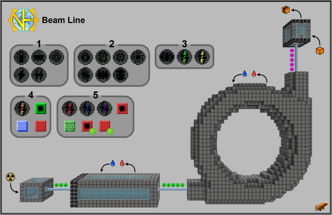
The Beam Line is a series of four ZPM tier multiblocks chained together with beam pipes and beam input/output hatches  , as seen in the following image. The beam pipes do not need to be colored but they cannot bend. The space between the multiblocks has no effect on the operation of the machine--build them as far apart or close together as preferred. For more specific construction requirements such as tiered components and material lists, visit the pages of the individual multiblocks.
Optionally, use the Beam Mirror, Beam Splitter, and/or Beam Stabilizer to redirect or optimize the particle beam as necessary. They really only assist with the Large Hadron Collider but they are fully compatible with the Beam Line as well. At no point can the particles be physically held or stored as an item.
Usage
The Beam Line is effectively a large laser engraver with its own configurable particle beam that determines which recipes the Target Chamber can run and how fast. The Beam Line is not actually required to progress but it is still recommended to build because its throughput is significantly higher than the Hyper-Intensity Laser Engraver (HILE) and the recipes themselves require fewer steps and resources. For example, the Beam Line can craft up to 512 PPIC wafers directly from a single doped wafer. The alternative is crafting up to 32 NPIC wafers from that same wafer and then consuming 64 indium gallium phosphide dust and 1,440L of sunnarium per NPIC wafer to refine each of them into PPIC wafers. The Beam Line consumes several long lanthanum hexaboride (LaB6) rods in the process, but it saves an incredible amount of indium gallium phosphide dust, sunnarium, and power in the end.
Recipes
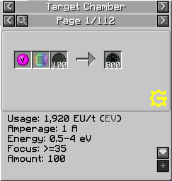
Beam Line recipes in NEI have only a photon, a mask, and doped wafers as input and engraved wafers as output. However, the photon is symbolic and not an actual item or input for the recipe. It is only there to establish that the final particle beam must specifically be a photon beam, not an electron beam or anything else. There are also a few extra requirements listed at the bottom of the recipe concerning the characteristics of the particle beam. The energy must be within a particular range, the focus must be greater than or equal to a certain value, and the base amount or rate determines the processing speed of the recipe.
Energy is primarily determined by the energy hatches on each of the machines as well as the length of the Linear Accelerator (LINAC). Focus always starts at a high value such as 90 or 95 and drops with each machine it passes through, but not as much with higher tier coolant. Amount or rate always starts at a low value such as 40 or 60 and is increased solely by concentrating power into the Synchrotron. The goal is to first meet the energy and focus requirements to run the recipe and then upgrading the energy hatches on the Synchrotron to make it faster without affecting any of the other stats. Multi-amp and laser energy hatches are supported for serious throughput.
Workflow
The general workflow for processing Beam Line recipes is listed below and explained in much more intricate detail in the following subsections about each of the individual multiblocks. Recommended setups and their construction requirements are then listed in the section after that.
| 1. The Source Chamber sets the initial stats of the particle beam based on the input or source material and the voltage of the machine. Of the seven possible source materials, long lanthanum hexaboride (LaB6) rods are by far the best but tungsten rods could be used as a backup. | ||
 Energy Focus Rate | ||
| 2. The Linear Accelerator (LINAC) accelerates the particle beam to boost its overall energy at the cost of focus. Increase the length of the LINAC or give it more power to strengthen the effect and reach higher energy levels. Supply coolant or super coolant to preserve the focus as much as possible in the process. The coolant is returned in full as its heated version which should be passively cooled and recycled. | ||
 Energy  Focus  Rate | ||
| 3. The Synchrotron accelerates the particle beam again until it produces a photon beam from the radiation of the high speed particles. Upgrade the antenna casings to keep the beam energy high and increase the beam rate more efficiently. Supply coolant or super coolant to again preserve the focus as much as possible in the process. The coolant is returned in full as its heated version which should be passively cooled and recycled. Supply as much power as reasonably possible through multi-amp and/or laser energy hatches because this is the only opportunity to increase the Beam Line's throughput. | ||
| Energy Focus Rate
| ||
| 4. The Target Chamber captures the final photon beam and does the actual laser engraving. The Target Chamber does not change any of the characteristics of the beam after it leaves the Synchrotron. It only checks that the beam energy and beam focus meet any recipe requirements and uses the beam rate to determine the duration of the recipe. The input bus next to the input side is for masks and the input bus next to the output side is for wafers. Masks determine the type of wafer to be engraved and are consumed in the process. | ||
Source Chamber
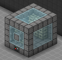
The Source Chamber is the first step in the Beam Line and generates a concentrated particle beam from very specific solid or liquid inputs, listed below in the following table. Source Chamber recipes are all one second long and output a single beam packet consisting of a particle type, energy, focus, and rate.
- Particle Type - The composition of the beam. Particles have a charge, rest mass, and their own max energy.
- Energy - The energy of the beam measured in electron volts (eV). Determines available recipes.
- Focus - The width of the beam. Minimum recipe requirement.
- Rate - The amount of particles per beam packet. Determines processing speed of recipes.
The input or source material is incredibly important because it determines the base stats of the particle beam. However, the only genuinely useful one is the long lanthanum hexaboride (LaB6) rod because it has reasonable energy levels and the highest beam rate, meaning it can process every recipe and rather quickly. Tungsten rods can be used as an alternative if lanthanum and borax are still difficult to produce. Two of the rows are grayed out because neutrons have neutral charge and therefore cannot be used in the Linear Accelerator or the Synchrotron; they are useless to the Beam Line.
| Source Material | Consumption | Min Power | Max Material Energy | Energy Ratio | Particle | Max Particle Energy | Focus | Rate | |
| Uranium-238 Dust | 1/s | 480 EU/t | 4,270 keV | 999 | Alpha | 8,000 keV | 90 | 1 | |
| Californium Dust | 1/s | 1,920 EU/t | 9,000 keV | 999 | Neutron | 15,000 keV | 95 | 10 | |
| Long Beryllium Rod | 1/s | 30,720 EU/t | 15,000 keV | 999 | Neutron | 15,000 keV | 95 | 10 | |
| Tungsten Rod | 1/s | 7,680 EU/t | 1,000 keV | 0.1 | Electron | 5,000 keV | 98 | 20 | |
| Long LaB6 Rod | 1/s | 7,680 EU/t | 5,000 keV | 0.3 | Electron | 5,000 keV | 99 | 60 | |
| Hydrogen Gas | 1,000 L/s | 491,520 EU/t | 1,000,000 keV | 0.3 | Proton | 1,000,000 keV | 99 | 40 | |
| Unstable Dust | 1/s | 1,966,080 EU/t | 1,700,000 keV | 0.3 | Omega | 1,700,000 keV | 99 | 60 |
The only other input to the Source Chamber is power and it determines the output beam energy, as seen in the following table. Multi-amp and laser energy hatches are not supported and there can only be one regular energy hatch, but the power requirements are very low anyway. For example, an LuV energy hatch is all that is needed to max out the beam energy for long LaB6 rods and upgrading it has no effect on the operation of the machine. Hydrogen gas requires a little bit more power but its low beam rate is not really viable for the Beam Line anyway.
| Source Material | Beam Energy vs. Energy Hatch | ||||
| IV | LuV | ZPM | UV | UHV+ | |
| Uranium-238 Dust | 4,270 keV | 4,270 keV | 4,270 keV | 4,270 keV | 4,270 keV |
| Californium Dust | 9,000 keV | 9,000 keV | 9,000 keV | 9,000 keV | 9,000 keV |
| Long Beryllium Rod | ---- | 15,000 keV | 15,000 keV | 15,000 keV | 15,000 keV |
| Tungsten Rod | 50 keV | 919 keV | 1,000 keV | 1,000 keV | 1,000 keV |
| Long LaB6 Rod | 712 keV | 4,997 keV | 5,000 keV | 5,000 keV | 5,000 keV |
| Hydrogen Gas | ---- | ---- | ---- | 999,946 keV | 1,000,000 keV |
| Unstable Dust | ---- | ---- | ---- | ---- | 1,700,000 keV |
Linear Accelerator
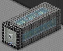
The Linear Accelerator (LINAC) is the second step in the Beam Line and accelerates particle beams by passing them through an electric field. This significantly increases the beam energy, slightly lowers the beam focus, but does not affect the beam rate. Increase the length of the LINAC or give it more power to strengthen the effect. The input beam energy is capped at 7,500 keV and the length must be an odd number between 19 and 83 blocks long.
The output beam focus depends on the input beam focus and the LINAC's own machine focus which is determined by the total length of the structure and the temperature (K) of the supplied coolant. There is no benefit to exceeding the minimum focus of recipes, but there is also no downside because there is no maximum.
Coolant is required for the machine to run and the temperature of it helps preserve the output beam focus. There are four types of coolant available and each one returns as the heated version of itself. Liquid oxygen can be pumped from Saturn with a Planetary Gas Siphon or extracted from space combs, liquid nitrogen can be extracted from glacial combs, hot coolant can be recycled and used for power in the Large Heat Exchanger, and hot super coolant can only be chilled inside a Vacuum Freezer.
| Coolant | Output | Temperature |
| Liquid Oxygen | Oxygen | 90 K |
| Liquid Nitrogen | Nitrogen | 77 K |
| Coolant | Hot Coolant | 60 K |
| Super Coolant | Hot Super Coolant | 1 K |
Synchrotron
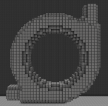
The Synchrotron is the third step in the Beam Line and accelerates the particle beam even more until it produces a photon beam from the radiation of the high speed particles. This changes the particle type to photon which is the one required for all Beam Line recipes and determines the final beam rate which is directly proportional to the processing speed of recipes. Upgrade the antenna casings to keep the beam energy high and increase the beam rate more efficiently. Upgrading the energy hatches increases the output beam energy up to a certain point, and then it only ever increases the output beam rate. The input beam focus must be greater than or equal to 25 for the Synchrotron to run.
The output beam focus again depends on the input beam focus and the Synchrotron's own machine focus which is determined solely by the temperature (K) of the supplied coolant. The options are the same four described earlier and they have the same effect of preserving the output beam focus. Coolant is consumed at a fixed rate of 32,000 L/s regardless of type and only ever needs to be supplied through one of the two input hatches.
Supply as much power as reasonably possible through multi-amp and/or laser energy hatches because this is the only opportunity to increase the Beam Line's throughput. Faster and larger crafts also indirectly provide an input discount because less source material is required if the Source Chamber does not have to run as often.
Target Chamber
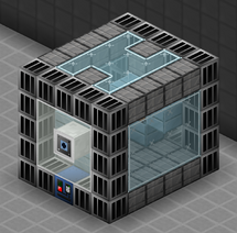
The Target Chamber is the fourth step in the Beam Line and captures the final photon beam to engrave any doped wafers. The Target Chamber does not change any of the characteristics of the beam after it leaves the Synchrotron. It only checks that the beam energy and beam focus meet any recipe requirements and uses the beam rate to determine the duration of the recipe, as seen in the following equation. Supplying more power than the minimum required has no effect on the operation of the machine because it does not overclock like a standard multiblock--concentrate power into the Synchrotron instead. The input bus next to the input side is for masks and the input bus next to the output side is for wafers.
The base amount varies with the recipe/mask and the doped wafer used, as seen in the following table. The input beam rate does not necessarily have to be greater than the base amount but that would cause the recipe to take longer than five seconds. The max throughput of the Target Chamber is consuming all masks of the same type in a single tick, which is more than enough at all stages of the game with compressed or quantum input buses. The photon in NEI is symbolic and not an actual item or input for the recipe. It is only there to establish that the final particle beam must specifically be a photon beam, not an electron beam or anything else.
| Output by Group | Mask Uses | Min Power | Beam Energy | Min Focus | Base Amount vs. Wafer Input | |||||||||
| Min | Max | Regular | P Doped | Nq Doped | Eu Doped | Am Doped | Ph Prepared | Ph Enhanced | Other | |||||
| 1 | ILC | 100 | 1,920 EU/t | 0.5 eV | 4 eV | 35 | 100 | 141 | 200 | 283 | 400 | 566 | 800 | ---- |
| RAM | 200 | 1,920 EU/t | 2 eV | 4 eV | 40 | ---- | 566 | 800 | 1,131 | 1,600 | 2,263 | 3,200 | ---- | |
| Simple SoC | 150 | 1,920 EU/t | 2 eV | 4 eV | 25 | 150 | 212 | 300 | 424 | 600 | 849 | 1,200 | ---- | |
| ULPIC | 200 | 1,920 EU/t | 2 eV | 4 eV | 30 | 200 | 283 | 400 | 566 | 800 | 1,131 | 1,600 | ---- | |
| LPIC | 150 | 1,920 EU/t | 2 eV | 4 eV | 30 | 300 | 424 | 600 | 849 | 1,200 | 1,697 | 2,400 | ---- | |
| 2 | SoC | 150 | 1,920 EU/t | 3 eV | 10 eV | 45 | ---- | ---- | 600 | 849 | 1,200 | 1,697 | 2,400 | ---- |
| QBit | 50 | 1,920 EU/t | 3 eV | 10 eV | 50 | ---- | 283 | 400 | 566 | 800 | 1,131 | 1,600 | ---- | |
| NanoCPU | 60 | 1,920 EU/t | 5 eV | 10 eV | 50 | ---- | 339 | 480 | 679 | 960 | 1,358 | 1,920 | ---- | |
| PIC | 100 | 1,920 EU/t | 5 eV | 10 eV | 50 | ---- | 566 | 800 | 1,131 | 1,600 | 2,263 | 3,200 | ---- | |
| CPU | 100 | 1,920 EU/t | 6 eV | 12 eV | 45 | 200 | 283 | 400 | 566 | 800 | 1,131 | 1,600 | ---- | |
| NAND | 200 | 1,920 EU/t | 7 eV | 12 eV | 40 | ---- | 283 | 400 | 566 | 800 | 1,131 | 1,600 | ---- | |
| NOR | 100 | 1,920 EU/t | 8 eV | 10 eV | 40 | ---- | ---- | 200 | 283 | 400 | 566 | 800 | ---- | |
| 3 | ASoC | 120 | 1,920 EU/t | 100 eV | 200 eV | 50 | ---- | ---- | 480 | 679 | 960 | 1,358 | 1,920 | ---- |
| HPIC | 80 | 1,920 EU/t | 100 eV | 200 eV | 50 | ---- | 679 | 960 | 1,358 | 1,920 | 2,715 | 3,840 | ---- | |
| UHPIC | 60 | 1,920 EU/t | 190 eV | 400 eV | 50 | ---- | ---- | 960 | 1,358 | 1,920 | 2,715 | 3,840 | ---- | |
| 4 | NPIC | 70 | 1,920 EU/t | 1,000 eV | 4,000 eV | 50 | ---- | ---- | ---- | 792 | 1,120 | 1,584 | 2,240 | ---- |
| Engraved Lapotron Chip | 120 | 30,720 EU/t | 1,000 eV | 3,000 eV | 50 | ---- | ---- | ---- | ---- | ---- | ---- | ---- | 360 | |
| Crystal CPU | 100 | 30,720 EU/t | 1,000 eV | 3,000 eV | 50 | ---- | ---- | ---- | ---- | ---- | ---- | ---- | 600 | |
| Crystal SoC | 100 | 30,720 EU/t | 2,000 eV | 7,000 eV | 50 | ---- | ---- | ---- | ---- | ---- | ---- | ---- | 800 | |
| 5 | PPIC | 50 | 1,920 EU/t | 1,500 eV | 10,000 eV | 50 | ---- | ---- | ---- | 849 | 1,200 | 1,697 | 2,400 | ---- |
| QPIC | 50 | 1,920 EU/t | 3,200 eV | 9,000 eV | 50 | ---- | ---- | ---- | ---- | 1,200 | 1,697 | 2,400 | ---- | |
| FPIC | 50 | 1,920 EU/t | 6,000 eV | 14,000 eV | 50 | ---- | ---- | ---- | ---- | 1,200 | 1,697 | 2,400 | ---- | |
| Raw Adv Crystal | 100 | 30,720 EU/t | 3,000 eV | 9,000 eV | 55 | ---- | ---- | ---- | ---- | ---- | ---- | ---- | 1,200 | |
| Living Crystal | 75 | 30,720 EU/t | 5,000 eV | 12,000 eV | 60 | ---- | ---- | ---- | ---- | ---- | ---- | ---- | 1,200 | |
| Crystal SoC CeLUAG | 100 | 30,720 EU/t | 5,000 eV | 12,000 eV | 60 | ---- | ---- | ---- | ---- | ---- | ---- | ---- | 2,400 | |
| Raw Adv Crystal CeLUAG | 100 | 30,720 EU/t | 6,000 eV | 14,000 eV | 70 | ---- | ---- | ---- | ---- | ---- | ---- | ---- | 3,600 | |
Recommended Setups
The wide range of beam energy, focus, and rate requirements mean that a single Beam Line is not enough for all possible recipes. At a minimum, there must be five Beam Lines with varying LINAC lengths, energy hatches, and coolant. The following groups are the wafers for each Beam Line and the tables are the recommended setups for those groups. Use the Beam Line calculator linked at the top for more details and/or custom setups.
Group 1 (2-4 eV)
|
Group 2 (8-10 eV)
|
Group 3 (190-200 eV)
|
Group 4 (2,000-3,000 eV)
|
Group 5 (6,000-9,000 eV)
|
Upgrade only the energy hatches on the Synchrotron to scale the throughput of the Beam Lines. Most of the other variables are designed specifically to stay within a particular energy range or above a minimum focus. The coolant in any group may be replaced with super coolant if preferred and the voltage of the Target Chamber is simply a minimum requirement that has no effect on the operation of the machine, since it does not overclock that way.
Long LaB6 Rods
Long LaB6 rods are the recommended source material for the Beam Line because they have a reasonable beam energy and the highest beam rate. All five setups can be made with a single LINAC, but the last group requires UEV voltage. That can be achieved with two UHV energy hatches but there are two alternatives if those are still out of reach. The first is increasing the LINAC length to 81 and reducing the voltage to UHV for a final beam energy of 5,168 eV and final beam focus of 61. That is not enough for the FPIC or raw advanced crystal CeLUAG recipes but it can process the rest. The other option is building a second LINAC immediately after the first. Their lengths should both be 29, their voltages should both be UHV, and they should both use super coolant. The final beam energy of 6,052 eV and beam focus of 79 is enough for all recipes in Group 5.
| Group | Source Chamber | Linear Accelerator | Synchrotron | Target Chamber | |||||||||||
| Input | Voltage | Length | Coolant | Voltage | Antennas | Coolant | Hatches | Energy | Focus | Rate | Voltage | ||||
| 1 | LaB6 | IV | 19 | Coolant+ | LuV | T2 | Coolant+ | 4x LuV+ | 2.81 eV | 59.9 | 12+ | EV+ | |||
| 2 | LaB6 | IV | 23 | Coolant+ | ZPM | T2 | Coolant+ | 4x ZPM+ | 8.24 eV | 57.6 | 25+ | EV+ | |||
| 3 | LaB6 | LuV | 25 | S. Coolant | ZPM | T2 | S. Coolant | 4x ZPM+ | 195.9 eV | 73.4 | 25+ | EV+ | |||
| 4 | LaB6 | LuV | 45 | S. Coolant | UHV | T2 | S. Coolant | 4x ZPM+ | 2,061 eV | 75.9 | 25+ | LuV | |||
| 5 | LaB6 | LuV | 57 | S. Coolant | UEV | T2 | S. Coolant | 4x UV+ | 6,077 eV | 70.9 | 51+ | LuV | |||
| Construction Requirements | ||
Group 1
|
Group 2
|
Group 3
|
Group 4
|
Group 5
|
Total
|
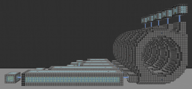
Tungsten Rods
Tungsten rods are NOT recommended for the Beam Line because they have a low beam energy and low beam rate, but they could be used as an alternative if LaB6 is not readily available yet. Three of the five setups require 2x LINACs to reach the higher energy ranges and the hatches on the Synchrotron must be a little better to reach the minimum beam rates.
| Group | Source Chamber | Linear Accelerator(s) | Synchrotron | Target Chamber | |||||||||||
| Input | Voltage | Length | Coolant | Voltage | Antennas | Coolant | Hatches | Energy | Focus | Rate | Voltage | ||||
| 1 | Tungsten | LuV | 23 | Coolant+ | IV | T2 | Coolant+ | 4x ZPM+ | 2.30 eV | 57.4 | 8+ | EV+ | |||
| 2 | Tungsten | LuV | 33 | S. Coolant | LuV | T2 | S. Coolant | 4x ZPM+ | 8.34 eV | 80.4 | 8+ | EV+ | |||
| 3 | Tungsten | LuV | 2x 41 | S. Coolant | LuV | T2 | S. Coolant | 4x UV+ | 195.0 eV | 71.5 | 17+ | EV+ | |||
| 4 | Tungsten | LuV | 2x 39 | S. Coolant | ZPM | T2 | S. Coolant | 4x UV+ | 2,126 eV | 72.8 | 17+ | LuV | |||
| 5 | Tungsten | LuV | 2x 29 | S. Coolant | UHV | T2 | S. Coolant | 4x UV+ | 6,052 eV | 79.0 | 17+ | LuV | |||
| Construction Requirements | ||
Group 1
|
Group 2
|
Group 3
|
Group 4
|
Group 5
|
Total
|
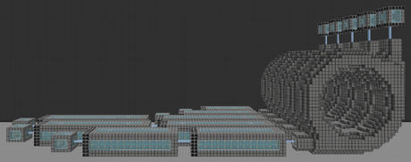
Automation
A Beam Line can run forever as long as there is source material, coolant, and power available. If left unchecked, that can waste a lot of resources and power while nothing is being crafted. Ideally, the Beam Line is only enabled whenever a recipe is available and disabled immediately after. It may also be useful to single-thread them, or preventing multiple from running simultaneously.
Method 1: GregTech
The core mechanic behind this approach is using a wireless item detector cover and wireless activity detector cover to enable the Source Chamber with an advanced wireless machine controller cover. Inputs are filtered between the input buses while the coolant and source material are passively stocked in the Source Chamber, LINAC, and Synchrotron. This approach is simple, compact, and scales well. There are no significant downsides. For versions 2.8 and earlier, use an advanced redstone receiver (internal) instead of the advanced wireless machine controller cover--they function exactly the same.
| STEP 1 | |
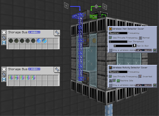
| Place an ME storage bus set to INSERT ONLY over both input buses on the Target Chamber. Filter them to the appropriate wafers and masks, respectively
Place a wireless item detector cover on the side of one input bus to emit a redstone signal if any items are present. Place an activity detector cover on the controller to emit a redstone signal if the Target Chamber is active. The frequencies are irrelevant as long as they match each other. Place a pair of kissing ME interfaces between the Beam Line subnetwork (blue) and the main network (green). Insert any patterns on the main network side. Power the Beam Line subnetwork with a quartz fiber cable, but upgrade to a neutronium energy anchor later on to save TPS in the late game. |
|
| STEP 2 | |
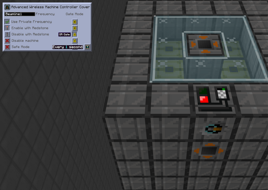
| If not single-threading, place an advanced wireless machine controller cover set to ENABLE WITH REDSTONE on the Source Chamber to automatically toggle it with either cover in the previous step. The LINAC and Synchrotron do not run if there is not an active beam so they do not need their own covers.
Use the same frequency as the covers in the previous step, but use different frequencies between Beam Lines to avoid enabling all of them at once when only one needs to run. Scaling this approach is as simple as increasing the batch size of crafts and the power supplied to the Synchrotron. None of the cover settings need to change. |
|
Optional: Single-Threading
Synchrotrons produce a lot of hot coolant and consume a lot of power when running multiple Beam Lines simultaneously. Without any controls in place, it may be difficult to sustain the maximum coolant throughput and caps each Synchrotron to a fraction of the total available power. The solution is single-threading, or preventing more than one Beam Line from running at a time. That significantly reduces the strain on the coolant recycling system and allows all available energy to concentrate on a single Synchrotron at a time. If done correctly, single-threading is no slower than multiple Beam Lines running simultaneously and is actually significantly faster when only one or two are needed, which is extremely common.
This approach uses the same covers on the Target Chamber as the steps above, but transmits their signals to a series of advanced redstone receivers instead of to the Source Chambers directly. A priority system involving OR and NOR gates then determines which Beam Line to run while disabling the rest. The example below prioritizes higher groups first, but it can be easily re-arranged to change the order if necessary. This approach is simple, compact, and scales well. There are no significant downsides.
| STEP 1 | |
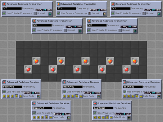
| Build the redstone control area somewhere in the same dimension as the Beam Lines. Start by placing five advanced redstone transmitters and five advanced redstone receivers as shown. The covers can be placed on machine hulls or frame boxes.
The receivers should have the same frequencies as the covers on the Target Chamber and their mode should be set to NOR gate. The transmitters should have different frequencies than the receivers and follow normal redstone behavior. Set all tick rates to 10 ticks to save on TPS. |
|
| STEP 2 | |
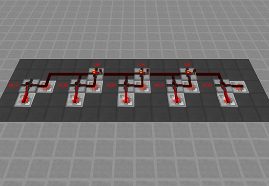
| Place red alloy wire, NOR gates, and OR gates as shown. These create a priority system that allows only one Beam Line to run at a time and favors higher groups first. For example, group 5 always runs before any of the other groups and group 1 always runs last.
Optionally, sneak right-click any of the gates to disable unused inputs. It is not necessary with the spacing shown but it could help condense everything even further. |
|
| STEP 3 | |
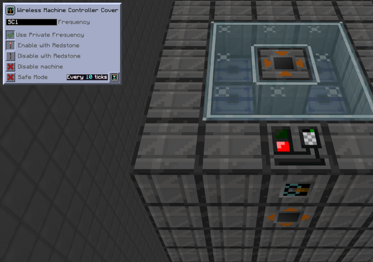
| Place a wireless machine controller cover set to ENABLE WITH REDSTONE on the Source Chamber to automatically toggle it with the transmitters in the redstone control area. The LINAC and Synchrotron do not run if there is not an active beam so they do not need their own covers.
Again, this frequency should be different from the one used for the covers on the Target Chamber. It should also be different from other Source Chambers. Set the tick rate to 10 ticks to save on TPS. |
|
Trivia
- The Beam Line is fully compatible with the Large Hadron Collider for engraving wafers. See the LHC page for details.