GT New Horizons · Ultimate Voltage (UV)
Network Switch With QoS
The Network Switch with QoS is a UV tier multiblock for splitting, joining, and routing computation generated by a Quantum Computer (QC). Conceptually, the Network Switch is very similar to an Active Transformer. Computation is inserted via optical reception connector(s) and extracted via optical transmission connector(s). The Quality of Service (QoS) or weight of each optical transmission connector is specified in the GUI of the controller and determines the total computation passed to each optical transmission connector. There is no maintenance requirement, but there is a power requirement that scales with the number of hatches. The only other way to split computation is to have multiple optical transmission connectors on the same QC to evenly distribute computation at the source.
Construction
The Network Switch is available as a fixed-length weighted version or a variable-length static version. They have different controllers but similar restrictions on buses/hatches. Optical reception connectors are limited to any advanced computer casing anywhere on the structure and the remaining buses/hatches may replace any regular or advanced computer casing anywhere on the structure. Multi-amp and Laser energy hatches are supported, but one regular energy hatch is usually enough anyway. The static structure does not require a maintenance hatch. Use the Multiblock Structure Hologram Projector to visualize/build the structure.
Static Structure
Each Additional Slice
|
Weighted Structure
|
Usage
Computation is inserted via optical reception connector(s) and extracted via optical transmission connector(s). They do NOT have to be painted the same color to route computation between them. The power consumption of the Network Switch is based on the following equation where C is the total number of optical connectors--maintenance and energy hatches are not included in the count.
Parameters
To route computation, set the LED parameters (destination and weight) of each optical transmission connector in the GUI of the controller. There are 10 pairs of LEDs to support up to 10 optical transmission connectors at once. For reference, the following image highlights the two configurable parameters for the first connector.
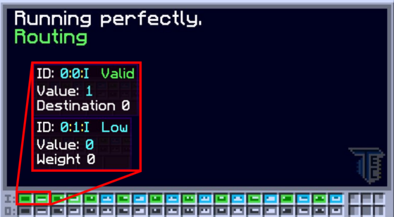
Destination - This parameter identifies the optical transmission connector to configure. Set the value to the ID shown when right-clicking an optical transmission connector with a Portable Scanner. The ID can change if any connectors are added or removed.
Weight - Computation is distributed on a weighted system. Optical transmission connectors with higher weights receive a larger proportion of the total computation and those with lower weights receive a smaller proportion. The weight can be any positive value and really depends on the application. Use the following equation to calculate the exact computation of an optical transmission connector from its weight.
Consider a Network Switch with three optical transmission connectors and weights of 1, 1, and 2. The total weight of this system is the sum of the individual weights or 4. This means that the first connector receives 1/4 of the total computation, the second connector receives 1/4 of the total computation, and the third connector receives 2/4 of the total computation.
 Important: | To specify exact computations instead of specific ratios, simply enter the computation value as the weight. This trick only works if EVERY weight is handled this way. For example, consider a Network Switch with 50,000 computation and 4 optical transmission connectors. Set the weights to 3000, 3000, 3000, and 41000 to route that exact amount of computation through each one of them. |
Trivia
- The location restriction on the optical reception connector is to prevent computation duping. Computation is never actually consumed and only ever "read" so the advanced computer casings are specifically in spots that stop the optical reception connector from being wallshared.