GT New Horizons · Insane Voltage (IV)
Precise Auto-Assembler MT-3662
The Precise Auto-Assembler MT-3662 (PrASS) is an IV tier multiblock for mass assembling and precise assembling. The PrASS is a direct upgrade from the singleblock assembler because it runs at 200% speed and offers up to 256 parallels based on the tier of the precise electronic unit casings. It also supports multi-amp and laser energy hatches for serious overclocking. The only downside is that it does NOT tier skip like the Large Scale Auto-Assembler v1.01 (e.g. no amount of ZPM amps can run UV recipes). Many of the casings can be replaced with buses/hatches to significantly reduce the cost of the structure and to facilitate input separation for a universal setup.
Construction
The PrASS has two different tiered components. The precise electronic unit casings limit the tier of the recipes in precise mode and determine the number of parallels in normal (assembler) mode. The machine casings limit the tier of the energy hatch and therefore the tier of the recipes in normal (assembler) mode. UHV machine casings unlock all energy hatches, but recipes are still capped at the average voltage tier. The glass can be anything EV+ and has no effect on the operation of the machine. Multi-amp and laser energy hatches are supported for serious overclocking, but the PrASS cannot tier skip. Use the Multiblock Structure Hologram Projector to visualize/build the structure with subchannels "unit_casing", "machine_casing", and "glass" to specify the tier of each of those components.
Structure
- Controller: Front bottom center
- 42-81 Precise Electronic Unit Casing (Tiered)
- 42 EV+ Tiered Glass
- 21 Machine Casing (Tiered)
- 12 Tungstensteel Frame Box
- 1+ Energy Hatch: Any unit casing
- 1 Maintenance Hatch: Any unit casing
- 1 Muffler Hatch: Any unit casing
- 1+ Input Bus: Any unit casing
- 0+ Input Hatch: Any unit casing
- 1+ Output Bus: Any unit casing
Wallsharing
PrASS may wallshare each of their sides to save on casings, frame boxes, and buses/hatches. Although it is possible to share the entire top of the structure and all 45 precise electronic unit casings, it is generally not recommended because that conflicts with most automation methods for a universal assembler. Only after the player has unlocked crafting input buffers is that a worthwhile strategy.
Usage
The PrASS is a direct upgrade from the singleblock assembler because it runs at 200% speed and offers up to 256 parallels based on the tier of the precise electronic unit casings, as seen in the following table. Note that the Mk-III unit casings are a UV recipe and therefore must be crafted in the Large Scale Auto-Assembler v1.01 to obtain them in ZPM.
| Mk-0 | Mk-I | Mk-II | Mk-III | Mk-IV | |
| Parallels | 16 | 32 | 64 | 128 | 256 |
| Tier Unlocked | IV | LuV | ZPM | ZPM | UHV |
The PrASS has two operating modes, listed below. Switch modes in the GUI of the controller, or by right-clicking the controller with a screwdriver. Both modes are not very particular on how ingredients are inserted so they can use the same automation setup. However, it eventually becomes necessary to build a second PrASS to avoid having to manually swap modes all the time.
- Normal Mode - Runs ONLY assembler recipes at 200% speed with up to 256 parallels depending on the tier of the unit casings.
- Precise Mode - Runs ONLY precise assembler recipes. There is no speed bonus or parallels.
Input separation  is permanently enabled on the PrASS which prevents SOLID ingredients in different input buses from being used in the same recipe, including any programmed circuits. That means a single PrASS with many input buses can support many different programmed circuits simultaneously--a universal assembler. Just don't forget to stay above the minimum number of precise electronic unit casings. FLUID ingredients are always shared regardless of input separation, unless the input hatch is colored.
Automation
The challenge in using the PrASS effectively is separating all possible programmed circuits. The minimum casing requirement is fairly low to support many different input buses/hatches, but it can still be difficult to avoid recipe conflicts.
Method 1: Applied Energistics
The core mechanic behind this approach is inserting ingredients into a subnetwork containing an input hatch and an input bus for each programmed circuit (PC). This design supports 18 input buses and 31 ME dual interfaces. This approach is simple and uses fewer components, but a few uncommon PC's may need to share the same input bus.
| STEP 1 | |
| Place input buses and input hatches on the top of the structure as shown. Also place an ME output bus somewhere in the middle row. The quadruple input hatch is for any precise assembler recipes.
The recommended PCs are 0, 0, 1, 1, 2, 3, 4, 5, 6, 7, 8, 9, 12, 16, 21, 22, 24, 24. Other PCs may be placed alongside one of those above. A conflict probably won't occur. |
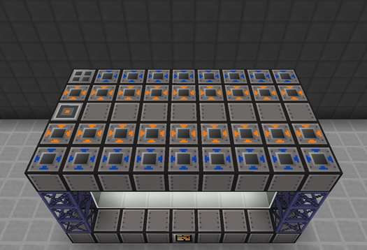
|
| STEP 2 | |
| Place an ME storage bus on each of the input buses and an ME fluid storage bus on each of the input hatches.
Place down alternating color cables to connect each bus/hatch pair. The image to the right uses blue and light blue, for example. Every bus/hatch pair is its own AE2 subnetwork. |
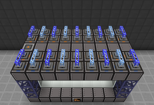
|
| STEP 3 | |
| Place dense fluix cable from the main network along the center row.
Power each subnetwork with a quartz fiber cable. This also separates the main network from the subnetworks. Later on, switch to neutronium energy anchors for better performance in the late game. The ME output bus connects directly to the dense fluix cable on the main network. |
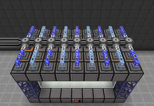
|
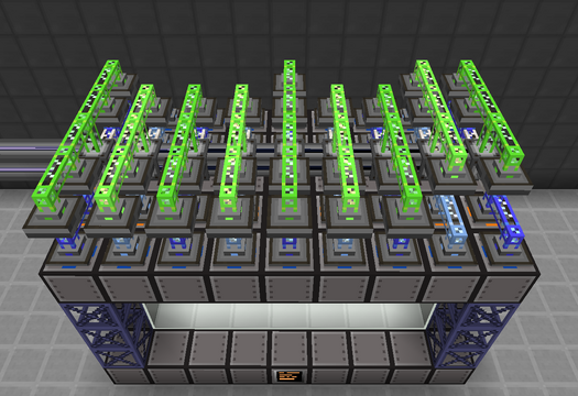
| STEP 4 | |
| Place ME dual interfaces on the blue and light blue cables to serve as the input for each subnetwork.
The number and placement of these dual interfaces are proportional to the amount of patterns that each subnetwork is expected to have. The patterns themselves do NOT go in these ME dual interfaces. |
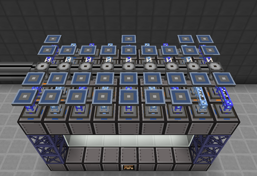
|
| STEP 5 | |
| Place an ME dual interface on top of each ME dual interface from the previous step.
Place down alternating color cables to connect the ME dual interfaces to the dense fluix cable. The image to the right uses green and lime, for example. The patterns go in the ME dual interfaces on top, the ones connected to the main network (green). Ensure that patterns are routed to the subnetwork with the correct PC. |
|
Method 2: Applied Energistics
The core mechanic behind this approach is inserting ingredients into a subnetwork containing only an input bus. Fluids are passed to adjacent subnetworks via fluid storage buses until they reach the input hatches on the edge of the structure. This design supports 31 input buses and 31 ME dual interfaces. This approach has more than enough input buses for all the different programmed circuits, but it uses significantly more components and is slightly more complicated to set up.
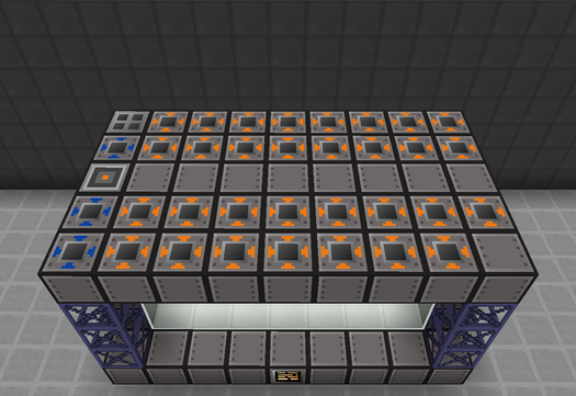
| STEP 1 | |
| Place input buses and input hatches on the top of the structure as shown. Also place an ME output bus somewhere in the middle row. The quadruple input hatch is for any precise assembler recipes.
The recommended PCs are 0, 0, 0, 0, 1, 1, 1, 1, 2, 2, 3, 3, 4, 4, 5, 6, 7, 8, 9, 10, 12, 16, 16, 21, 22, 24, 24, 24, 24. Other PCs may be placed alongside one of those above. A conflict probably won't occur. |
|
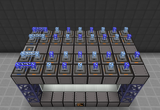
| STEP 2 | |
| Place an ME storage bus on each of the input buses and an ME fluid storage bus on each of the input hatches.
Place down alternating color cables on the storage buses so that none of them connect to each other. The image to the right uses blue and light blue, for example. The fluid storage buses can share the same color cable as their adjacent storage bus. Every input bus is its own AE2 subnetwork. |
|
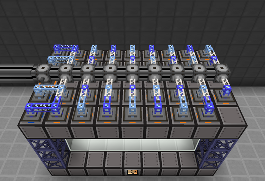
| STEP 3 | |
| Place dense fluix cable from the main network along the center row.
Power each subnetwork with a quartz fiber cable. This also separates the main network from the subnetworks. Later on, switch to neutronium energy anchors for better performance in the late game. Cable anchors are used in the first column because those subnetworks are already receiving power from the quartz fiber cable in the second column. The ME output bus connects directly to the dense fluix cable on the main network. |
|
| STEP 4 | |
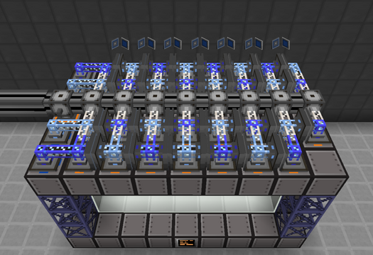
| Place fluid storage buses leading towards the input hatches on the edge of the structure. Face them directly into an ME dual interface on the adjacent subnetwork.
Every pair of "kissing" components in the image to the right has an ME dual interface on the left and a fluid storage bus on the right. This pushes all fluids through each subnetwork until they reach the input hatches on the edge of the structure. |
|
| STEP 5 | |
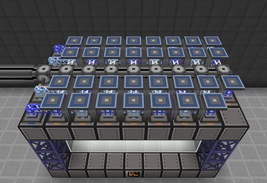
| Place ME dual interfaces on the blue and light blue cables to serve as the input for each subnetwork.
The patterns themselves do NOT go in these ME dual interfaces. |
|
| STEP 6 | |
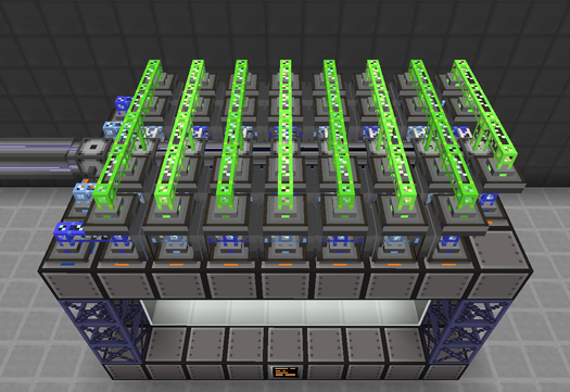
| Place an ME dual interface on top of each ME dual interface from the previous step.
Place down alternating color cables to connect the ME dual interfaces to the dense fluix cable. The image to the right uses green and lime, for example. The patterns go in the ME dual interfaces on top, the ones connected to the main network (green). Ensure that patterns are routed to the subnetwork with the correct PC. |
|
Other Methods
Although there is support for multi-amp and laser energy hatches, the imperfect overclocks eventually push the player into building more PrASS to keep up with longer/bigger crafts. The above methods turn into a bottleneck because it lacks scalability and is limited by the size of the input buses. The solution is to leverage the auto-pull mechanic of advanced stocking buses/hatches in a universal automation setup which allows any number of PrASS to pull from the same set of ingredients while keeping the programmed circuits separate.
The final solution to automating the PrASS is replacing most of the unit casings with crafting input buffers. Not only does that forego all of the cabling, interfaces, and storage buses but it can even be shared by two PrASS simultaneously.