GT New Horizons · Ultimate Voltage (UV)
Extreme Temperature Fluctuation Purification Unit
The Extreme Temperature Fluctuation Purification Unit (TPU) is a UV tier multiblock used for the fifth step of the Water Line. It uses temperature fluctuations to purify water, by first heating it to very high temperatures using plasma, and then cooling it back down using coolant. It is required in UV in order to process americium doped wafers, which are needed for the Fusion Reactor Mk-III and many other recipes in UHV and beyond.
Construction
The TPU has no tiered components or energy hatches because it receives power directly from the Water Purification Plant once linked with a data stick, like the rest of the Water Line multiblocks. Use the Multiblock Structure Hologram Projector to visualize/build the structure.
Structure
- Controller: Front bottom center
- 672 Reinforced Sterile Water Plant Casing
- 64 Tinted Industrial Glass (any color)
- 50-53 Heat-Resistant Trinium Plated Casing
- 40 Superconductor Base ZPM Frame Box
- 9 Superconducting Coil Block
- 8 Neonite (any color)
- 3+ Input Hatch: Bottom left of chamber (plasma), front bottom center of tower (coolant), any trinium casing (water)
- 1+ Output Hatch: Any trinium casing
Mechanics
See More: Waterline#Shared Mechanics
The TPU maintains an internal temperature value, which begins at 0K at the start of a recipe cycle. It will consume Helium Plasma and Super Coolant from their Input Hatches in order to change the temperature: it can consume up to 10 L/s of Helium Plasma, with each increasing the temperature by 100K, and up to 100 L/s of Super Coolant, with each lowering the temperature by 5K. As a result, the temperature change per second is capped at 1,000K upwards and 500K downwards. The aim is to raise the temperature to 10,000K and then lower it to 0K again; the success chance begins at 0%, and each such cycle of raising and lowering the temperature will increase it by 33%. The recipe will also fail if it ever reaches 12,500K or more, producing steam instead.
Automation
There are many methods of automating the TPU, but only one is discussed in detail here due to its simplicity and ease of implementation.
Method 1: State Cell
The core mechanics behind this approach are that ProjectRed State Cells can be used to delay a redstone signal for a precise length of time, and that Fluid Regulators can be used to send a precise amount of fluid into an input hatch upon receiving a redstone signal. This can be used to move the exact amount of Helium Plasma to add 10,000K at the start of every heating cycle, and the exact amount of Super Coolant to subtract that 10,000K as soon as it is reached.
| STEP 1 | |
| Place two Wireless Activity Detector Covers on the controller, and give them two different frequencies. Set one to "Machine idle" and Inverted, and the other to "Recipe progress". | 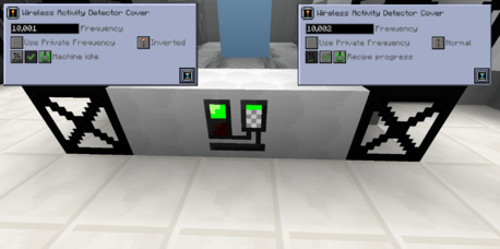
|
| STEP 2 | |
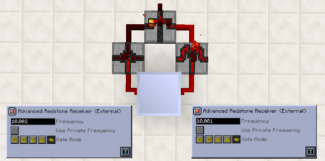
| Place a Machine Hull somewhere else, and place two Advanced Redstone Receivers (External) on it, set to the two frequencies from before. Set both to "Analog" for their Gate Mode.
Connect the one on the same frequency as the "Recipe progress" cover to a NOT Gate using Red Alloy Wire, and then connect the NOT Gate's output to an AND Gate. Connect the one on the same frequency as the "Machine idle" cover to a Buffer Gate, and connect that to the same AND Gate. Shift-right click the AND Gate with a Screwdriver to disable the third input. |
|
| STEP 3 | |
| Place a Pulse Former on the output of the AND Gate. Run a wire from its output and place three State Cells on each side. On one side, set the intervals to 1, 31, and 61 seconds; this is for Helium Plasma. On the other, set them to 11, 41, and 71 seconds; this is for Super Coolant. Run a wire between the outputs of the State Cells on each side, and place a Wireless Transmitter on them, with different frequencies. | 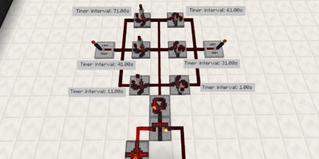
|
| STEP 4 | |
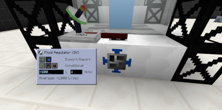
| Place a Wireless Receiver next to the Helium Plasma Input Hatch. Place a Machine Controller Cover on it, and run Red Alloy Wire so it can power the Machine Controller Cover.
Place a Fluid Regulator on the Input Hatch, and set it to "Use Machine Processing State" and to import 100L every 2 ticks. |
|
| STEP 5 | |
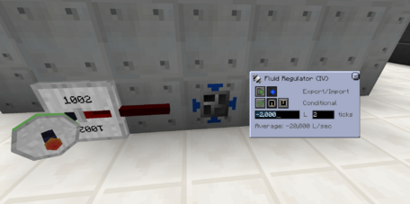
| Place a Wireless Receiver next to the Super Coolant Input Hatch. Place a Machine Controller Cover on it, and run Red Alloy Wire so it can power the Machine Controller Cover.
Place a Fluid Regulator on the Input Hatch, and set it to "Use Machine Processing State" and to import 2000L every 2 ticks. |
|
| STEP 6 | |
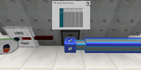
| Place a Dual Interface adjacent to the Fluid Regulator on each Input Hatch, and set it to stock the respective fluid. Ensure both are connected to an ME system with a passive supply of Helium Plasma and Super Coolant.
Although only the Super Coolant hatch is shown here, the Helium Plasma one should be set up the same way. |
|