GT New Horizons · Extreme Voltage (EV)
Lapotronic Supercapacitor
The Lapotronic Supercapacitor (LSC) is an EV tier multiblock for storing and transforming power. The total energy storage, or capacity, of the LSC depends on the number and tier of the capacitors built into the structure. Capacitors range from EV to UMV and increase in energy storage by an order of magnitude with each tier, except the last few tiers (UHV and up) which instead increase the wireless EU threshold. There is no transfer limit on energy/dynamo hatches, but at least UV glass is needed for laser hatches. The only downside to the LSC is that it suffers from passive energy loss of 1% of the total energy storage per 24 hours, but that is a very small price to pay for centralized power. Automate generators with energy detector cover(s) and an RS latch circuit to avoid wasting power.
Construction
The LSC can be anywhere between 4 and 50 blocks tall depending on the number of capacitors. No air is allowed inside the structure, but not all capacitors need to be the same tier and only a majority need to be non-empty. For example, a minimum height LSC may contain 3 IV capacitors, 2 EV capacitors, and 4 empty capacitors. The glass is a tiered component and must be no less than three tiers below the highest tier capacitor for the structure to form. Multi-amp and laser energy hatches are supported but the latter requires at least UV tier glass. Use the Multiblock Structure Hologram Projector to visualize/build the structure with subchannels "glass" and "capacitor" to specify the tier of those components and subchannel "height" to specify the total height of the capacitor stack (1-47).
Base Structure
|
Each Additional Layer
|
Wallsharing
LSCs may wallshare each of their sides to save on casings and glass. However it is highly unnecessary and not recommended because a single LSC can have many energy/dynamo hatches and up to 432 capacitors which is more than enough energy storage at all stages of the game.
Usage
The LSC is effectively a large battery buffer. The total energy storage, or capacity, depends on the number and tier of the capacitors built into the structure. More specifically, it is the sum of the capacitors' individual capacities. Not all capacitors need to be the same tier and only a majority (>50%) need to be non-empty. The last few tiers also support wireless EU which is covered in the next section.
Passive Power Loss
While running, the LSC loses 1% of its total energy storage per 24 hours. This loss is increased by an additional 0.2% per maintenance issue before ultimately shutting down with six maintenance issues. The loss should never be a significant problem for the player as long as the total capacity does not far exceed the average power intake. That means do not add capacitors to an LSC if they are never going to be filled. Use the following equation to calculate the loss in EU/t from the total capacity of the LSC, assuming no maintenance issues.
The last few tiers of capacitors have incredibly high capacities and do not follow the same equation. Instead, the passive power loss starts at 1,000,000 EU/t for each UHV capacitor and increases by two orders of magnitude (100x) for every tier above. The following table lists all the available capacitors as well as their individual capacity and minimum loss. Note that filling one UMV capacitor with 128 Eye of Harmony and zero power consumption takes approximately 8.22e13 years or 18,108 times the age of the Earth.
| Capacitor | Capacity | Loss | Wireless |
| Empty | 0 EU | 0 EU/t | ✗ |
| EV | 60,000,000 EU | -0.3472 EU/t | ✗ |
| IV | 600,000,000 EU | -3.472 EU/t | ✗ |
| LuV | 6,000,000,000 EU | -34.72 EU/t | ✗ |
| ZPM | 60,000,000,000 EU | -347.2 EU/t | ✗ |
| UV | 600,000,000,000 EU | -3,472 EU/t | ✗ |
| UHV | 9,223,372,036,854,775,807 EU | -1,000,000 EU/t | ✓ |
| UEV | 9,223,372,036,854,775,807 EU | -100,000,000 EU/t | ✓ |
| UIV | 9,223,372,036,854,775,807 EU | -10,000,000,000 EU/t | ✓ |
| UMV | 85,070,591,730,234,615,847,396,907,784,232,501,249 EU | -1,000,000,000,000 EU/t | ✓ |
Hatches
Power is inserted via energy hatches and extracted via dynamo hatches. There is no limitation on the tier, amount, or size of the hatches other than the minimum casing requirement of the structure. The energy and dynamo hatches do not even need to be the same tier; the player can mix and match different voltages almost like a transformer. However, at least UV glass is needed for laser source and laser target hatches.
The only other type of hatch that the LSC requires is a maintenance hatch. The player should check the maintenance hatch regularly because it increases the passive power loss of the machine. It may be useful to place a Needs Maintenance Cover on the LSC and connect that to a howler alarm or other signal that immediately notifies the player of the issue.
Operational Data
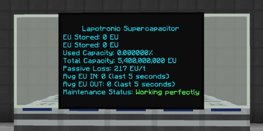
View the operational data (used capacity, total capacity, etc.) in the GUI of the controller, or by right-clicking the controller with a Portable Scanner. To display the data externally, right-click the controller with a GregTech sensor kit to receive a sensor card for an industrial information panel. Add information panel extenders around it to widen the screen and provide a redstone signal to turn it on. All lines are displayed by default, but the less useful ones can be hidden by unchecking the corresponding box in the GUI of the information panel. There is also an advanced version which does not require a redstone signal and allows customization of the color, thickness, and tilt of the screen.
The operational data can even be displayed on the player's HUD through OpenComputers AR Glasses. Setting that up from scratch can be quite complicated so try using Networked Information Display & Automation Software (NIDAS) or following the steps here: OC Power Display.
Upgrading
The capacitors, glass, and energy/dynamo hatches constantly need to be upgraded as the player progresses. However, it can be very problematic if the centralized power of a base is shut down for even a few seconds to make adjustments. Many machines can power fail and then require a manual restart afterwards. The Drone Centre makes it easy to re-enable machines, but the better solution is to hot-swap components. The LSC runs a structure check every few seconds which leaves a small amount of time to quickly break and replace a block or two at a time.
Hot-swapping an energy/dynamo hatch should be easy enough, but the other components are slightly more difficult. The capacitors, for instance, require breaking and replacing a glass block in addition to the capacitor itself--two different blocks within the same time window. Alternatively, the capacitors can be replaced directly with the Ring of Loki by creating an offset that reaches perfectly inside the LSC as shown in the image below. Ensure Loki breaking mode is enabled and that you have sufficient mana before attempting this.
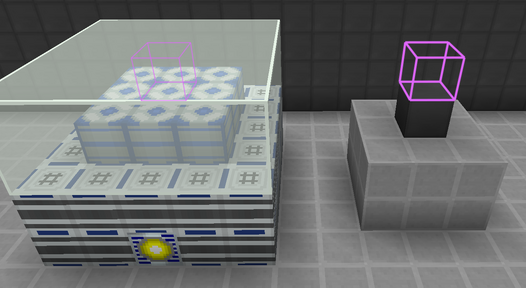
Hot-swapping the glass is most easily done with a Mk-II Matter Manipulator. The Ring of Loki can also do it fairly easily, but that requires setting many different offsets (highlighted blocks) at once. Another option is to use the Wand Focus of Equal Trade, although not all the glass can be replaced at once. Good luck.
The last option is to setup multiple battery buffers (or even a second LSC) to temporarily supply power to a base. There is no risk when swapping out components this way, but it is far more expensive and time consuming. Note that laser hatches naturally function as a temporary battery buffer because they have very large internal capacities.
Wireless Mode
The last few tiers of capacitors (UHV+) unlock the ability for the LSC to transfer EU wirelessly. Once formed, enable wireless mode in the GUI of the controller or by using a screwdriver on the controller. Nothing will really change about the LSC itself, but now it will either upload or download EU from a player's wireless network every 6,000 ticks (five minutes). The direction depends on whether the internal capacity is above or below the wireless threshold. If below, the LSC attempts to download EU from the wireless network up to the wireless threshold. If above, the LSC uploads all EU over the wireless threshold to the wireless network. Note that there is a button in the GUI of the controller to force a wireless rebalance outside the typical five minute cycle, but it has a one time use.
Wireless Network
The wireless network itself is effectively an infinite amount of storage or 2^(2^31) EU with no passive power loss. The amount of wireless EU in a network is visible with the rest of the operational data in the various locations discussed earlier, or by equipping unlinked Power Goggles. Wireless networks are normally private, but all members of a team can join the same network by using either the spaceproject (sp) or GregTech (gt) commands below. The latter requires OP.
User Commands
/sp invite <name>sends invite to player./sp accept <player>accept invite from player./sp leaveleaves the team, needs to be confirmed./sp confirmconfirms the leave.
Admin Commands
/gt global_energy_join <name> <host>adds a player to the host's wireless network. Only the host can execute this command./gt global_energy_join <name> <name>returns a player to their own wireless network./gt global_energy_display <name>displays the current EU in a player's wireless network./gt global_energy_set <name> <amount>sets a player's wireless network to a specific amount of EU./gt global_energy_add <name> <amount>changes a player's wireless network by a specific amount of EU (positive or negative).
Wireless Threshold
The wireless threshold of an LSC is determined by the number and tier of the capacitors built into the structure. More specifically, it is the sum of the capacitors' individual thresholds. For example, an LSC with two UHV capacitors has a wireless threshold of 60T + 60T = 120T EU which means that it downloads EU from a wireless network until its internal capacity exceeds 120T EU, and then begins uploading to the wireless network instead. Every capacitor tier above UHV increases the wireless threshold by two orders of magnitude (100-fold).
Note that the wireless threshold mechanic really only limits the download speed of the LSC and NOT the upload speed. This means a single UHV capacitor is more than enough for any number of Dyson Swarm Ground Units uploading to the wireless network, but at least a UEV capacitor is required to download all the power from just one--and up to two more.
The following table summarizes the effective EU/t of each of the wireless capacitors based on their wireless thresholds and the time between rebalances. For example, an LSC equipped with a brand new UEV capacitor gains 6P EU at the start of the next cycle and should not use more than 476,837A UHV to avoid running out of power within the next 5 minutes.
| Capacitor | Threshold | Max EU/t | Amps (UHV) | Amps (UEV) | Amps (UIV) | Amps (UMV) | Amps (UXV) | |||||
| UHV | 6e+13 | 60 T | 1e+10 | 10 B | 4,768 | 1,192 | 298 | 74 | 18 | |||
| UEV | 6e+15 | 6 P | 1e+12 | 1 T | 476,837 | 119,209 | 29,802 | 7,450 | 1,862 | |||
| UIV | 6e+17 | 600 P | 1e+14 | 100 T | 47,683,715 | 11,920,928 | 2,980,232 | 745,058 | 186,264 | |||
| UMV | 6e+19 | 60 E | 1e+16 | 10 P | 4,768,371,582 | 1,192,092,896 | 298,023,224 | 74,505,806 | 18,626,451 | |||
Automation
The LSC is often accompanied by an RS latch to automatically turn off generators such as Large Steam Turbines or Large Gas Turbines when the energy capacity is close to full. The goal is to prevent excess fuel consumption during periods of low power consumption, and to maximize efficiency for machines with long warm-up periods.
RS latch stands for set-reset latch and it is a basic circuit for storing a single binary value. The RS latch outputs a high value (1) whenever the set signal is activated and outputs a low value (0) whenever the reset signal is activated. If neither signals are activated, then the RS latch maintains its last known state. It should not be possible for both signals to be activated at the same time because that can lead to an unpredictable output. This is extremely useful for the LSC because a set signal can enable generators when power is low and a reset signal can disable generators when power is high. It is impossible to quickly jump between states which makes this ideal for large turbines with long warm-up periods and any machine that voids excess EU.
Method 1: Two Energy Detector Covers
The core mechanic behind this approach is using two energy detector covers for the set and reset signals. This requires less redstone and no magic progression, but it occupies two sides of the LSC controller.
| STEP 1 | |
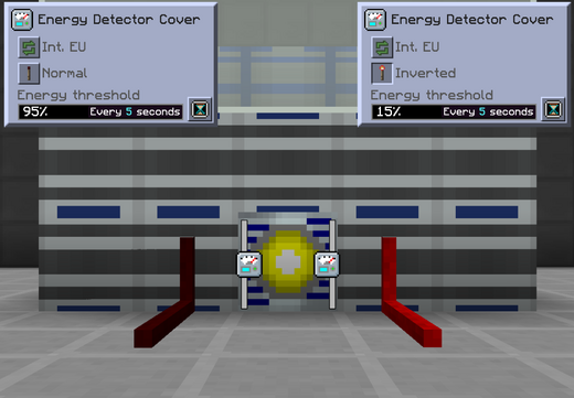
| Place an energy detector cover set to read INTERNAL EU on either side of the LSC. Set the tick rates to 5 seconds to save TPS.
On the HIGH side, set the threshold to 95% of the total capacity with NORMAL redstone behavior. On the LOW side, set the threshold to 15% of the total capacity with INVERTED redstone behavior. Use a soldering iron on the energy detector covers to set their signal strength to STRONG, allowing them to transmit through the casings on either side of the controller. Use red alloy wire to carry the redstone signal along any surface, and/or framed red alloy wire to carry it through open space. |
|
| STEP 2 | |
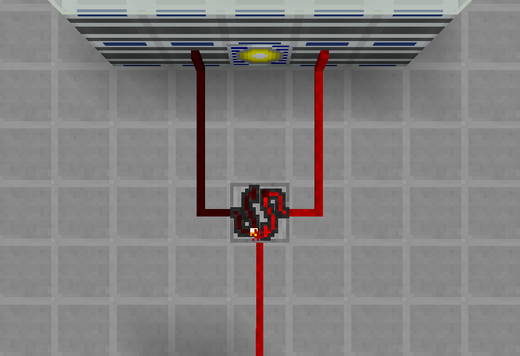
| Place an RS latch gate and connect the input sides to the energy detector covers in the previous step. Sneak right-click the RS latch with a screwdriver (twice) to change its configuration.
The LOW side sends a set signal, enabling the redstone output. The HIGH side sends a reset signal, disabling the redstone output. |
|
| STEP 3 | |
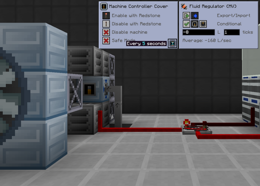
| Place a machine controller cover set to ENABLE WITH REDSTONE on the side of the generator(s) input hatch. Set the tick rate to 5 seconds to save TPS.
Change the settings of the fluid regulator to USE MACHINE PROCESSING STATE to control it with a machine controller cover. The energy detector covers enable the generator(s) when power is less than 15% and disable them when power is greater than 95%. Change the energy detector settings to change these percentages. |
|
| STEP 4 | |
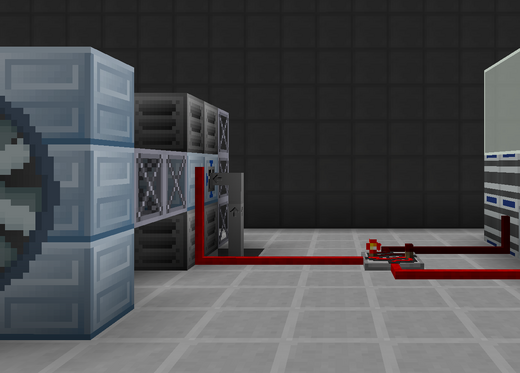
| Place the remaining blocks to complete the structure and run the red alloy wire over the side to reach the machine controller cover.
Wireless redstone transmitters and receivers may be easier to use instead of red alloy wire depending on the particular setup. Parallelizing this approach is as simple as extending the same signal to other generators. |
|
Method 2: One Energy Detector Cover (Magic)
The core mechanic behind this approach is using Dense Red Crystals from Thaumcraft to set the minimum and maximum thresholds for the set and reset signals. Only one energy detector cover is necessary, but it requires magic progression.
| STEP 1 | |
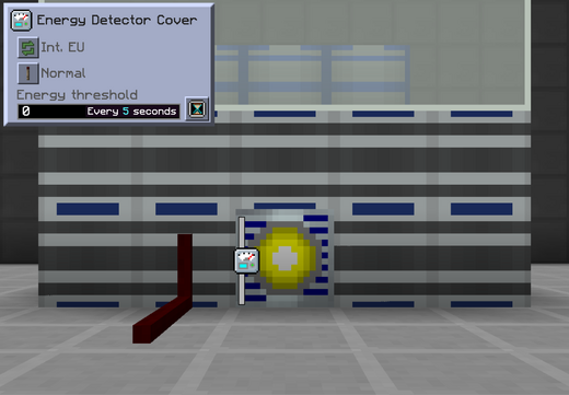
| Place an energy detector cover set to read INTERNAL EU on the side of the LSC. Set the tick rate to 5 seconds to save TPS.
Use a soldering iron on the energy detector cover to set its signal strength to STRONG, allowing it to transmit through the casing on the side of the controller. This outputs a redstone signal with a strength proportional to the current capacity. Use red alloy wire to carry the redstone signal along any surface, and/or framed red alloy wire to carry it through open space. |
|
| STEP 2 | |
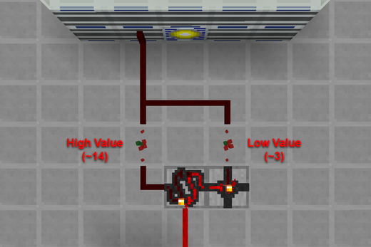
| Build the RS latch circuit as seen in the image to the right. The bottom center component is an RS latch and the bottom right component is a NOT gate. The other two components are dense red crystals from TC.
Sneak right-click the RS latch with a screwdriver (twice) to change its configuration. Sneak right-click the NOT gate with a screwdriver to disable any unused outputs. Right-click the dense red crystals with a wand to change their signal strength. Set the left crystal to a high value (~14) and the right crystal to a low value (~3). |
|
| STEP 3 | |
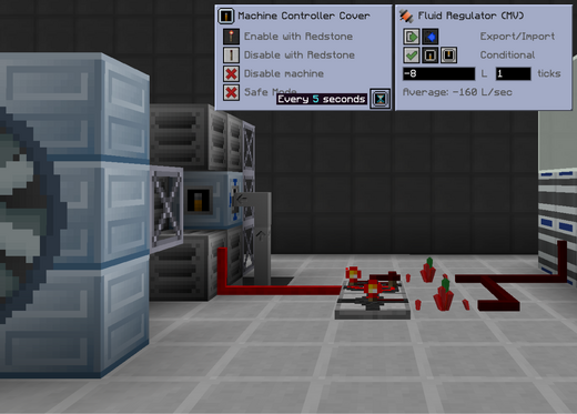
| Place a machine controller cover set to ENABLE WITH REDSTONE on the side of the generator(s) input hatch. Set the tick rate to 5 seconds to save TPS.
Change the settings of the fluid regulator to USE MACHINE PROCESSING STATE to control it with a machine controller cover. The left crystal enables the generator(s) when power is less than ~15%. The right crystal disables the generator(s) when power is greater than ~92%. Change the strength of the Dense Red Crystals to change these percentages. |
|
| STEP 4 | |
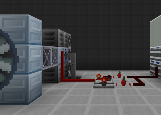
| Place the remaining blocks to complete the structure and run the red alloy wire over the side to reach the machine controller cover.
Wireless redstone transmitters and receivers may be easier to use instead of red alloy wire depending on the particular setup. Parallelizing this approach is as simple as extending the same signal to other generators. |
|
Method 3: One Energy Detector Cover (No Magic)
The core mechanic behind this approach is using potentiometers from Draconic Evolution to set the minimum and maximum thresholds for the set and reset signals. Only one energy detector cover is necessary and no magic is required.
| STEP 1 | |
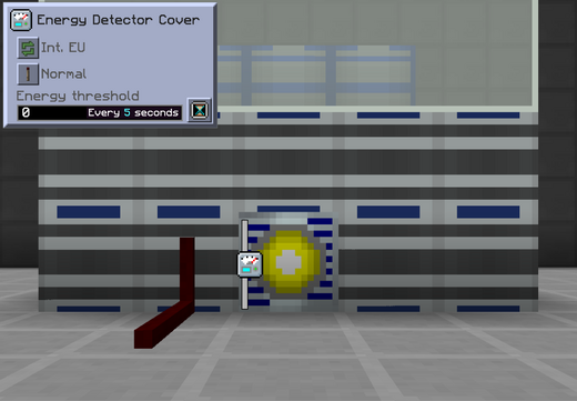
| Place an energy detector cover set to read INTERNAL EU on the side of the LSC. Set the tick rate to 5 seconds to save TPS.
Use a soldering iron on the energy detector cover to set its signal strength to STRONG, allowing it to transmit through the casing on the side of the controller. This outputs a redstone signal with a strength proportional to the current capacity. Use red alloy wire to carry the redstone signal along any surface, and/or framed red alloy wire to carry it through open space. |
|
| STEP 2 | |
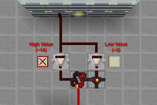
| Build the RS latch circuit as seen in the image to the right. The bottom center component is an RS latch and the bottom right component is a NOT gate. The other two components are vanilla comparators. The small blocks next to the comparators are potentiometers.
Sneak right-click the RS latch with a screwdriver (twice) to change its configuration. Sneak right-click the NOT gate with a screwdriver to disable any unused outputs. Right-click the potentiometers to change their signal strength. Set the left one to a high value (~14) and the right one to a low value (~3). |
|
| STEP 3 | |
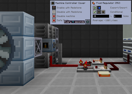
| Place a machine controller cover set to ENABLE WITH REDSTONE on the side of the generator(s) input hatch. Set the tick rate to 5 seconds to save TPS.
Change the settings of the fluid regulator to USE MACHINE PROCESSING STATE to control it with a machine controller cover. The left potentiometer enables the generator(s) when power is less than ~15%. The right potentiometer disables the generator(s) when power is greater than ~92%. Change the strength of the potentiometers to change these percentages. |
|
| STEP 4 | |
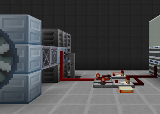
| Place the remaining blocks to complete the structure and run the red alloy wire over the side to reach the machine controller cover.
Wireless redstone transmitters and receivers may be easier to use instead of red alloy wire depending on the particular setup. Parallelizing this approach is as simple as extending the same signal to other generators. |
|