GT New Horizons · Medium Voltage (MV)
Fluid Drilling Rig
The Fluid Drilling Rig (FDR) is an MV tier multiblock for harvesting large fluid reservoirs underneath bedrock. Fluid reservoirs are the size of 8x8 regular chunks and vary significantly in both the type and amount of fluid, especially across planets or dimensions. Prospect fluid reservoirs and add their information to Journey Map by right-clicking bedrock with a prospector's scanner, or by using a seismic prospector. Higher tiers of the FDR have a higher minimum voltage but a larger range so they can pull from more chunks at the same time. The final tier can gather an infinite amount of fluid across an entire reservoir. The rate at which fluid is extracted is determined by the number of voltage tiers above the minimum and the remaining amount of fluid within the operating range. Transport fluids to/from your base with long distance fluid pipelines, ME quantum rings, or ender tanks. The Fluid Drilling Rig is superseded by the Space Elevator in UHV.
Construction
The FDR has no tiered components. The glass on the Infinite FDR can be any tier and has no effect on the operation of the machine. Insert mining pipes in the controller and/or an input bus. The mining pipe physically spawns in the world underneath the center block of the structure and destroys everything in its path as it travels straight down to bedrock. Multi-amp and laser energy hatches are not supported and only ONE regular energy hatch is allowed. Each tier of the FDR also requires a minimum voltage to run. Use the Multiblock Structure Hologram Projector to visualize/build the structure with subchannel "glass" to specify the tier of the glass for the infinite FDR.
 Caution: | Don't forget to protect the machine from rain and/or meteors! |
Base Structure
Tier 1
Tier 2
Tier 3
Tier 4
|
Infinite
|
Wallsharing
FDRs may wallshare each of their sides to save on casings, frame boxes, and buses/hatches. The FDR only consumes 0.875A of power so it is possible to share one energy hatch between two machines.
Fluid Reservoirs
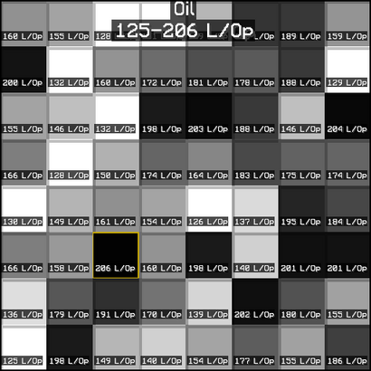
Fluid reservoirs generate underneath bedrock and are the size of 8x8 regular chunks. The type and amount of fluid in a reservoir can vary significantly, especially across planets or dimensions. For example, the Overworld has various oil and natural gas reservoirs while the Moon has salt water and helium-3 reservoirs. Check the recipes of a fluid or the uses of a planet block in NEI to see all of its underground fluid stats.
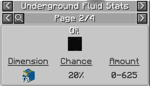 |
Every chunk within a reservoir contains the same fluid but those amounts/rates can vary significantly too, as seen in the upper right image. L/Op means liters per operation and it is the amount an FDR can pump from that chunk every few ticks. The symbolic NEI amounts are exactly twice the displayed L/Op values on JourneyMap. Anything above 100 L/Op is pretty good.
Fluid reservoirs are created during World Generation and are unknown to the player until prospected, much like ore veins. Right-click bedrock with a prospector's scanner to share information about the current reservoir to the JourneyMap underground fluid overlay. It is recommended to dig down at the very corner of a reservoir to scan up to three more in quick succession. Alternatively, use a seismic prospector to learn about nine reservoirs at once (3x3 centered on the machine). A Portable Scanner can also detect the amount of fluid in a chunk, but does not share the information with the Journeymap underground fluid overlay. The chunk(s) with the highest amount/rate have a yellow outline on the overlay.
The listed amounts/rates do NOT automatically update over time; re-prospect the reservoir to see the latest values. The Journey Map underground fluid overlay may also need to be disabled and re-enabled to properly update. There is no way to mark a fluid reservoir as depleted like with ore veins, but their color naturally fades over time as they are drained.
Usage
Once enabled, the FDR deploys its mining pipe(s) straight down towards bedrock which can take a few seconds depending on the current y-level of the machine. If necessary, press the "abort and retract mining pipes" button inside the GUI of the controller to immediately stop the process. An output bus cannot be added to the structure so the mining pipes are returned to the slot inside the controller. The FDR starts pumping fluid as soon as the mining pipes reach bedrock but not while the mining pipes are still deploying or retracting.
All FDRs come with a built-in option to enable chunkloading, but it ONLY applies to the chunk that the machine is in. The rest of the operating range must be manually claimed and chunkloaded with ServerUtilities or world anchors for the FDR to pull from them. The built-in option is primarily for keeping a metrics transmitter cover active.
Use programmed circuits to ignore near exhausted fluid reservoirs/chunks. The FDR automatically stops and retracts its mining pipes whenever the L/Op is less than the programmed circuit number.
The Infinite FDR is unique because it offers 2 parallels per energy hatch tier above UHV, as seen in the following table. The power panel may list only one parallel but the pump rate should increase accordingly.
| UHV | UEV | UIV | UMV | UXV | MAX | MAX+ | |
| Parallels | 1 | 3 | 5 | 7 | 9 | 11 | 13 |
Range
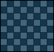
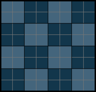
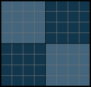
The specific chunks that an FDR pulls from depends on the tier of the machine and its location within a fluid reservoir. Higher tiers have larger ranges and can pull from multiple chunks simultaneously, as seen in the following table and images. However, the ranges are relative to the reservoir itself instead of being centered on the controller. That means an FDR pulls from the same chunks regardless of where it is within that group; the FDR has to move to an entirely different group to pull from a different set of chunks. There is no overlap and there is no pulling from two different reservoirs at the same time.
Right-click the controller with a screwdriver to reduce the operating range, if absoutely necessary. The range can even be an odd number such as 3x3 or 5x5 despite not fitting perfectly inside an 8x8 chunk fluid reservoir. In those cases, the left-most and bottom-most groups are cut short. The benefit is that the base operation time is halved with each decrement, but the downside is that it lowers the total amount of fluid available and therefore the fluid extraction rate. In general, reducing the range is not worth it at all and the player should keep to the maximums.
|
|

Yield
The amounts listed in NEI are only a symbolic value. The actual yield of a reservoir is significantly higher and can be approximated with the following equation. The summation is only if there are multiple chunks within the same operating range. The error is less than 0.1% for amounts greater than 31L.
The fluid rates are slightly more complicated and depend on the voltage tier of the energy hatch. First calculate the speed of the FDR with the following equation where the difference is simply the number of voltage tiers above the minimum. Exceeding the minimum voltage tier also halves the base operation time per tier. The power consumed is always 0.875A at the current voltage.
The L/Op values listed on JourneyMap assume the lowest possible speed or 50%. The actual rates depend on the underlying amount, as seen in the following equation which uses a floor operator to round values down to the nearest integer. Divide this rate by the number of ticks in an operation to determine the fluid extraction rate in L/t.
The amount of fluid drained from each chunk is different from the amount of fluid extracted and only depends on the speed of the FDR, as seen in the equation below. Notice that this rate does not depend on the current amount of fluid in the chunk and therefore does not slow down as a chunk is depleted--it is effectively constant. The infinite FDR ignores this completely and never drains any amount of fluid from any chunk.
Use the drainage rate to determine the lifespan of a chunk or group of chunks. Divide by the number of ticks in an operation to determine the lifespan in ticks. Divide even further to determine the lifespan in seconds, minutes, or even hours.
Example
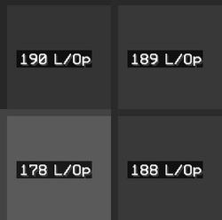
Consider a T2 FDR with an EV energy hatch (1 tier above the minimum) and the default range of 2x2 chunks. Let it run in an oil reservoir over the four chunks shown in the image to the right. Start with some basic calculations to gather more information about the machine and the operating area.
- Amount = (190 + 189 + 178 + 188) x 2 = 1,490 L
- Speed = 0.50 + 0.25(4 - 3) = 0.75
- Ticks/Op = 8 / 2 = 4 Ticks
Next, calculate the total yield and fluid rates. However, the extraction rate decreases as the chunks are depleted so the value here is the absolute max. Divide by two to find the average.
- Yield = 500 x (3802 + 3782 + 3562 + 3762) = 277,698,000 L
- +L/Op = 1,490L x 0.75 = 1,117 L/Op
- -L/Op = 0.75 / 1000 = 0.00075 L/Op
Turn these values into usable rates by dividing by the number of ticks per operation. The lifespan is based on the chunk with the single highest value because all four chunks are depleted equally as fast.
- +L/t = 1,117 / 4 = 279 L/t
- -L/t = 0.00075 / 4 = 0.0001875 L/t
- Lifespan = 380L / 0.0001875 = 2,026,666 Ticks or approximately 28h 9m.
Sample Calculations
The following are some sample calculations to provide a reference when scanning fluid reservoirs. The amounts are the summation of all chunks within the operating range and the values in parentheses are the number of voltage tiers above the minimum. There is an assumption that the base operation time is 8 ticks so these do not apply to the infinite FDR.
| Amount | Base Rate | Yield | Output Rate (T+0) | Output Rate (T+1) | Output Rate (T+2) | Output Rate (T+3) | ||||||||
| Max | Avg | Max | Avg | Max | Avg | Max | Avg | |||||||
| 30 | 15 L/Op | 450,000L | 1.88 L/t | 0.94 L/t | 5.63 L/t | 2.81 L/t | 15.0 L/t | 7.50 L/t | 37.5 L/t | 18.8 L/t | ||||
| 50 | 25 L/Op | 1,250,000L | 3.13 L/t | 1.56 L/t | 9.38 L/t | 4.69 L/t | 25.0 L/t | 12.5 L/t | 62.5 L/t | 31.3 L/t | ||||
| 100 | 50 L/Op | 5,000,000L | 6.25 L/t | 3.13 L/t | 18.8 L/t | 9.38 L/t | 50.0 L/t | 25.0 L/t | 125 L/t | 62.5 L/t | ||||
| 200 | 100 L/Op | 20,000,000L | 12.5 L/t | 6.25 L/t | 37.5 L/t | 18.8 L/t | 100 L/t | 50.0 L/t | 250 L/t | 125 L/t | ||||
| 400 | 200 L/Op | 80,000,000L | 25.0 L/t | 12.5 L/t | 75.0 L/t | 37.5 L/t | 200 L/t | 100 L/t | 500 L/t | 250 L/t | ||||
| 600 | 300 L/Op | 180,000,000L | 37.5 L/t | 18.8 L/t | 113 L/t | 56.3 L/t | 300 L/t | 150 L/t | 750 L/t | 375 L/t | ||||
| 800 | 400 L/Op | 320,000,000L | 50.0 L/t | 25.0 L/t | 150 L/t | 75.0 L/t | 400 L/t | 200 L/t | 1000 L/t | 500 L/t | ||||
| 1,000 | 500 L/Op | 500,000,000L | 62.5 L/t | 31.3 L/t | 188 L/t | 93.8 L/t | 500 L/t | 250 L/t | 1,250 L/t | 625 L/t | ||||
Logistics
The best reservoirs are not always nearby. It is very common for the FDR to be separated from a player's main base, such as on a different planet. Fortunately, there are a few ways to transport power and fluids across long distances or dimensions. The following lists some of the most popular methods.
Method 1: Long Distance Fluid Pipeline
This method is the cheapest and earliest available option. However, it is slightly difficult to construct or deconstruct for an FDR that is very far away. Long distance fluid pipelines also cannot cross dimensions.
| STEP 1 | |
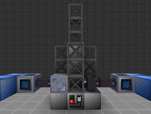
| The image to the right uses TWO separate long distance fluid pipelines to simultaneously provide fuel AND return the output fluid. Recall that long distance fluid pipelines must span at least 64 blocks (4 chunks) and do not auto-push or auto-pull fluids.
The left one provides diesel for the singleblock combustion generator on site and the right one sends oil back to the base for desulfurization and distillation. Diesel and other liquid fuels are very energy dense so another viable strategy is to just leave a pre-filled tank out next to the combustion generator. In that case, only a long distance fluid pipeline is needed for the output. |
|
Method 2: Quantum Ring
This method is fairly expensive and requires some basic knowledge of AE2. There is also more idle power consumption and power penalties.
| STEP 1 | |
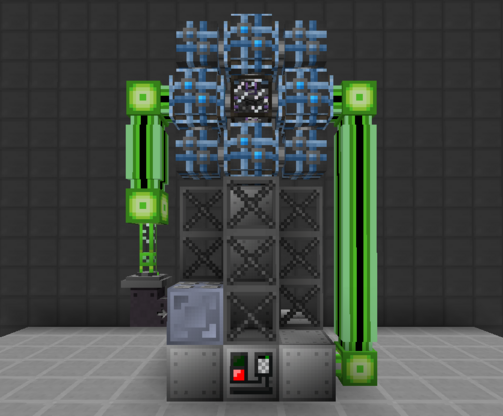
| A quantum ring provides a local connection to the main network (green). Recall that quantum rings need a jump-start on the receiving end before they can receive any power from the other end. Try bringing a filled dense energy cell along with you--break with a wrench to retain the power.
On the left side of the quantum ring is a fluid P2P tunnel providing fuel for the singleblock combustion generator on site. Create a fluid P2P tunnel by placing a regular P2P tunnel and right-clicking it with a fluid cell. Use a memory card or advanced memory card to link it. On the right side of the quantum ring is an ME output hatch providing the output fluid directly to the main network. It may be helpful to include an ME storage cell for a larger buffer. Singleblock generators for higher voltage tiers are not very fuel efficient. It may be better to use an EU P2P tunnel instead. Create one by placing a regular P2P tunnel and right-clicking it with a GregTech cable. |
|
Method 3: Ender Tanks
This method is by far the easiest and quickest to setup, but requires Thaumcraft progression and/or luck with lootbags.
| STEP 1 | |
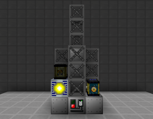
| The image to the right uses TWO separate ender tanks to simultaneously provide fuel AND return the output fluid. Recall that Ender Tanks must match the color combination on top to link.
The left one provides helium plasma for the singleblock plasma generator and the right one sends chlorobenzene back to the base for electrolyzing. Plasmas are extremely energy dense so another viable strategy is to just leave a pre-filled tank out next to the plasma generator. However, that creates a manual task at a point where most everything should be automated. |
|
Trivia
- Placing warded glass directly below the FDR tricks it into thinking that it reached bedrock.
- Prior to Version 2.8.0, the FDR was called the Oil/Gas/Fluid Drilling Rig